What this guide proves
The robot has one unambiguous base frame and measured transforms to its LiDAR and optional RGB-D camera. RViz can display the physical arrangement without a guessed axis or duplicated transform publisher.
Hardware and scope boundary
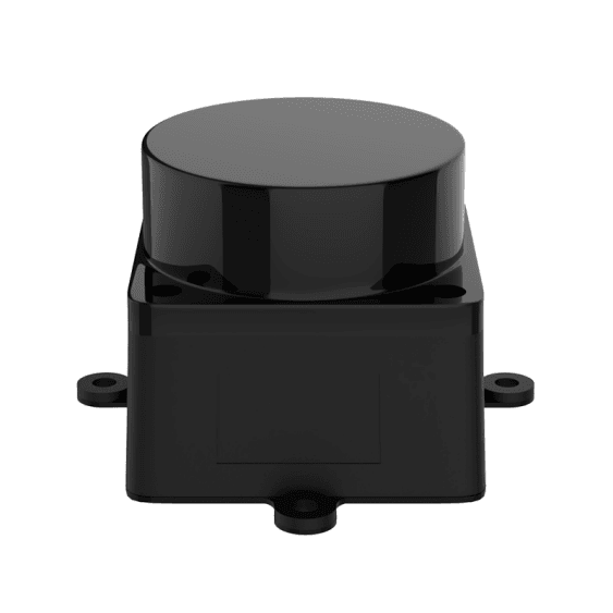
COG-T1-TRACK-BASE is the mobile structure. COG-MS200-LIDAR supplies one horizontal 2D scan plane; COG-AURORA930-PRO supplies aligned depth, RGB and IR streams. COG-RPI5-8GB hosts ROS 2 and COG-RRC-LITE may provide low-level feedback, but neither product defines the final transforms for a custom installation.
Prepare before applying power
Mount sensors rigidly, route cables without crossing the MS200 scan plane, and measure from a reproducible physical reference. Record forward direction, mounting height, yaw orientation and whether the camera optical frame follows its driver convention.
Procedure
- Choose base_link at a stable, documented chassis reference and define x forward, y left and z up consistently across URDF, controller and navigation parameters.
- Add fixed transforms only from measured values. Use temporary static transforms for bench validation, then move final values into the robot description or approved launch configuration.
- Check the LiDAR frame while the robot is still. A known target placed in front of the chassis must appear in the expected forward direction; do not compensate a reversed scan with a map setting.
- For Aurora930 Pro, inspect RGB, depth, IR and camera optical frames from the delivered driver. Confirm the parent frame and alignment behavior before consuming depth in an application.
- Visualize the complete TF tree and sensor data in RViz. Restart the launch system once to detect duplicate broadcasters or transforms that exist only in a local shell.
Pass criteria and record
Save the URDF/Xacro source, measured transform table, sensor mounting photos and a TF-tree snapshot. The same result must return after reboot and when the robot is placed in a known orientation.
Do not proceed when
Do not map, navigate or plan arm motion with a guessed sensor axis, conflicting TF publishers, a LiDAR frame that sees forward as another direction, or an unverified camera optical-frame convention.
Continue from here
Feed only this verified geometry into LiDAR SLAM, RGB-D processing and any arm-to-base transform for mobile manipulation.