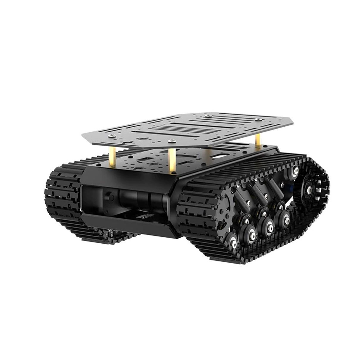
What this guide proves
A Cogalloy T1 Advanced-compatible tracked base responds predictably to low-speed linear and angular commands while an operator can stop it immediately. The goal is to verify the motion chain, not to declare the chassis autonomous.
Hardware and scope boundary
COG-T1-TRACK-BASE includes its own two 12 V Hall-encoder motors, 4-channel driver, 11.1 V / 6000 mAh pack and 12.6 V charger. Host computer, sensors and ROS software are separate. Do not substitute COG-7V4-2200-LIPO for the included pack or charger path without an explicit, verified system design.
Prepare before applying power
Inspect the track tension, motor PH2.0-6P connectors, controller wiring and build-specific emergency-stop or power-disconnect method. Choose an open, supervised test area; keep the first motion test slow and use a physical way to remove drive power.
Procedure
- Confirm that the host, low-level controller and chassis firmware agree on left/right motor mapping and encoder direction before publishing any ROS velocity command.
- With the tracks safely clear of the ground when appropriate, issue a very small forward command and verify both sides drive in the intended direction. Repeat for reverse, left yaw and right yaw.
- On the ground, use a controlled keyboard or joystick teleoperation source to publish cmd_vel at a conservative speed. Verify that releasing the input or stopping the node produces the documented safe stop behavior.
- Record the linear and angular speed limits, command timeout and any deadband configured by the delivered controller firmware.
- Compare encoder change and IMU response against each supervised movement. A direction mismatch must be fixed at the mapping level, not hidden by a later navigation parameter.
Pass criteria and record
The chassis moves only after an explicit command, stops predictably, turns in the commanded sense, and reports feedback consistent with observed motion. Save the motor map, speed limits and test video or log.
Do not proceed when
Do not continue to SLAM or navigation if a track direction, encoder sign, timeout or stop behavior is ambiguous; if the base browns out; or if the test area cannot remain supervised.
Continue from here
Calibrate odometry and coordinate frames, then introduce a LiDAR only after the raw scan and mechanical mounting have separately passed acceptance.