What this guide proves
RPLIDAR C1 produces continuous, correctly oriented LaserScan data that can be recorded and checked against real targets. The result establishes sensor acceptance; it does not prove every obstacle material is detectable.
Hardware and scope boundary
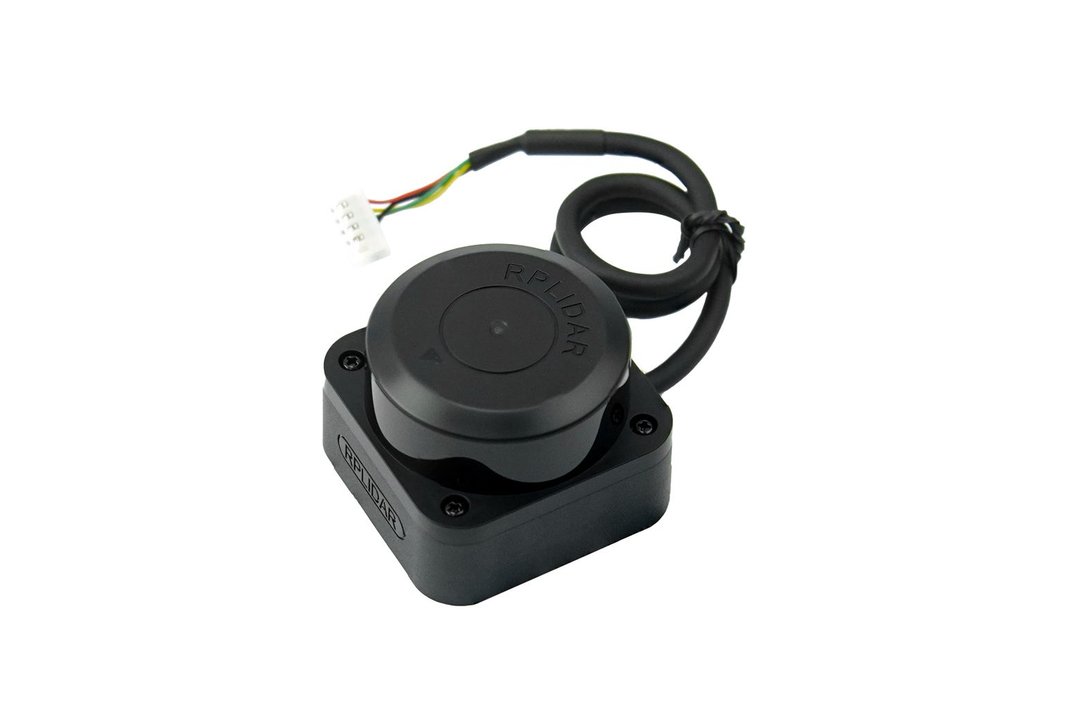
SENSOR-001 is a 360° single-line fusion dToF LiDAR. It uses 4.8–5.2 V power, 3.3 V TTL UART at 460800 baud and an XH2.54-5P connector. Its 10 Hz startup budget can be much higher than steady current, so power design must account for the published startup reference rather than only the typical operating current.
Prepare before applying power
Use the delivered pinout to verify 5 V, TX, RX and GND before connection. Mount through the specified bottom holes without exceeding the allowed screw insertion depth, keep the optical window and scan plane clear, and supply a stable 5 V rail.
Procedure
- Confirm connector orientation, UART logic level and baud rate with the delivered documentation. Do not connect a 5 V serial signal to a 3.3 V data pin.
- Start the approved driver or SDK path on the Raspberry Pi host and inspect raw scan output before adding TF, SLAM or navigation.
- Place known light and dark targets at conservative distances and record whether scan coverage, range and angle appear stable under the actual room lighting.
- Validate the documented scan convention: forward is +X and angle increase is clockwise in the published convention. Align the ROS frame explicitly rather than assuming another LiDAR convention.
- Record a short bag or driver log while the sensor and robot are stationary, then repeat after a controlled low-speed movement to expose power or cable-intermittency faults.
Pass criteria and record
The acceptance record includes delivered firmware/driver identity, pinout confirmation, power observation, static target data, frame orientation and a saved raw-scan sample.
Do not proceed when
Stop if the optical window is blocked, the rail droops at startup, the serial connection is unverified, the frame is reversed, or target behavior is not stable enough for the intended environment.
Continue from here
Introduce the verified scan into the LiDAR SLAM guide, keeping final map and navigation limits conservative until the completed robot has been tested.