 1 / 3
1 / 3RPLIDAR C1 360° Fusion dToF 2D LiDAR
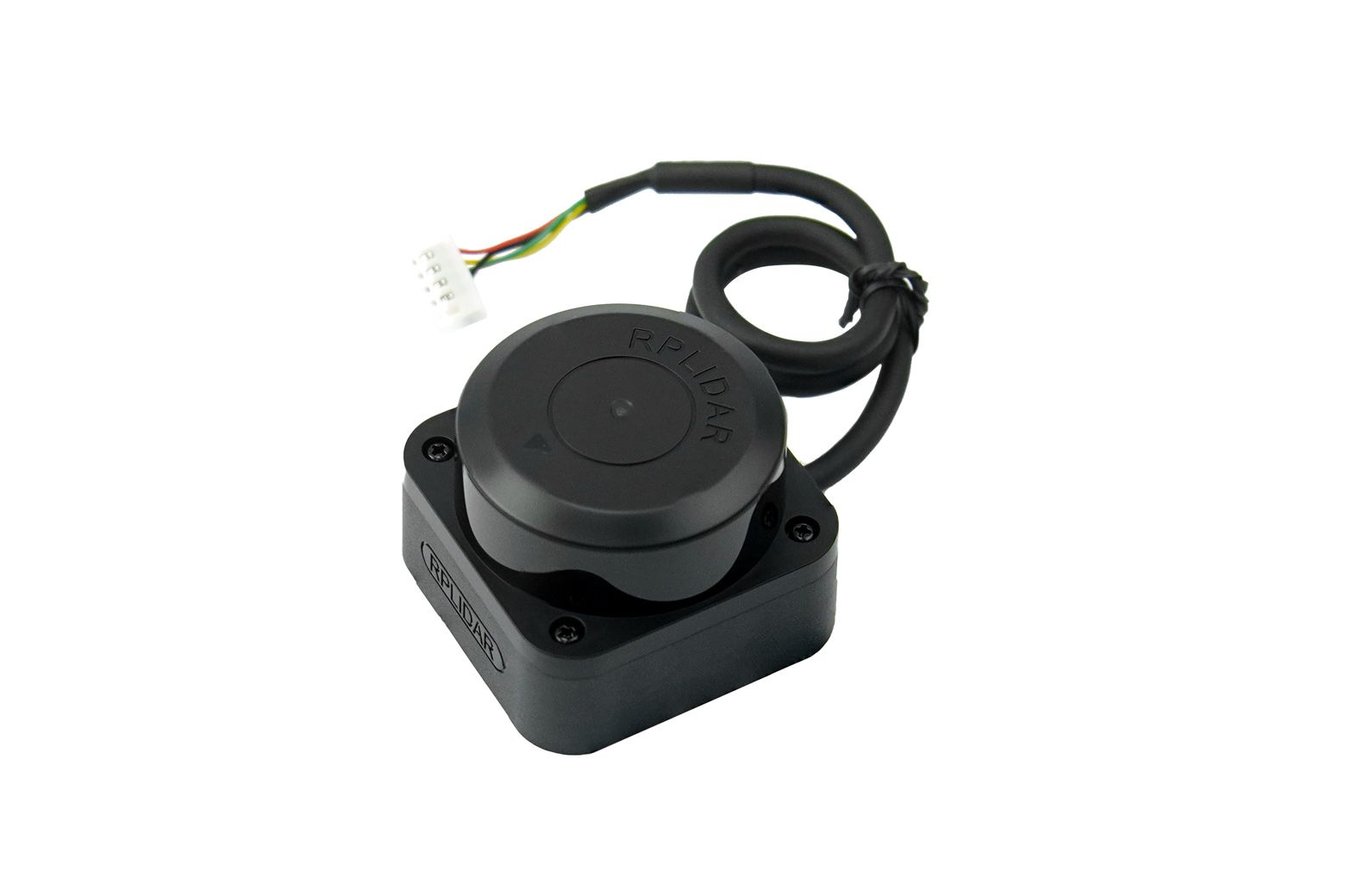
RPLIDAR C1 is a 360° single-line fusion dToF LiDAR for ROS / ROS 2 mapping, localization and planar obstacle perception. Choose it over COG-MS200-LIDAR when you value the published 10%-reflectivity black-target range, 5 kHz / 0.72° scan density at 10 Hz and IP54 protection; allow for its 110 g body and 5 V start-up budget.
- 5 kHz / 0.72° at 10 Hz: Higher published point density for a rotating 2D navigation scan.
- Range stated by target surface: 0.05–12 m on 70% white and 0.05–6 m on 10% black targets.
- IP54 + documented RPLIDAR path: Useful when enclosure exposure and a mature SDK / ROS ecosystem are priorities.
- Plan the real power path: Use stable 5 V power and allow for 800 mA typical start-up current at the sensor.
Price
US$127.00
No account or payment needed. We usually confirm availability, lead time, shipping, and total price within 12 hours.
Or email us directly: sales@cogalloy.comShipping options and final delivery cost are shown at checkout.
SYSTEM ROLE
Publish one reliable navigation plane.
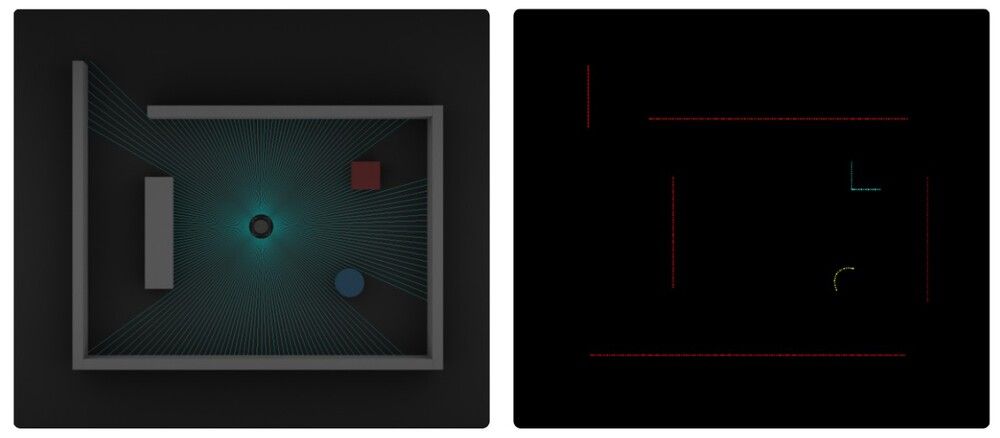
C1 is a planar LiDAR. It turns a rotating horizontal scan into distance and angle data for mapping, localization and obstacle logic; it does not provide the vertical scene geometry of a depth camera or 3D LiDAR.
- 360° scan coverage for a mobile-base perception layer.
- Use the scan with a correct sensor frame and robot-to-sensor transform.
- Place the scan plane at the height of the obstacles that genuinely matter.
MEASUREMENT REALITY
Compare surface-conditioned range, not only “12 m”.
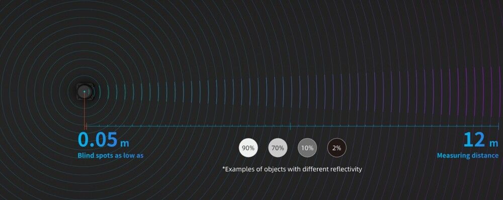
C1 publishes both a 12 m figure for a 70% reflective white target and a 6 m figure for a 10% reflective black target. That is a more useful selection input than treating every material as a white wall.
- Published blind range: 0.05 m.
- Published accuracy: ±30 mm; published ranging resolution: 15 mm.
- Test dark, glossy, transparent, angled and low obstacles on the finished robot.
INTEGRATION PATH
Protect the optical path and the power budget.
Use the 3.3 V TTL UART at 460800 baud with separate stable 5 V power. The scanner needs a clear optical window, a rigid level mount and a supply that can support the published start-up current; all three affect the quality of the scan you receive.
- XH2.54-5P power / UART connection; do not connect UART logic to an incompatible voltage.
- At 10 Hz: 230 mA typical and 260 mA maximum operating current; 800 mA typical start-up current.
- Keep bottom M2.5 screw insertion at or below 4 mm to avoid internal damage.
SELECTION GUIDE
When C1 is the better choice than COG-MS200-LIDAR.
Choose C1 when your decision prioritizes published low-reflectivity target behavior, 5 kHz / 0.72° typical scan density at 10 Hz, IP54 protection and the RPLIDAR integration ecosystem. Choose MS200 instead when the robot has a strict 40 g / compact 4-pin-UART packaging constraint.
- Both are single-plane 2D LiDARs: neither replaces a depth camera or 3D LiDAR.
- Do not compare the two “12 m” claims as if they used the same reflectivity condition.
- Select after checking installed height, power, connector, target material and robot speed.
Related tutorials
Build with your parts
IntermediateRPLIDAR C1: LaserScan Bring-Up and Acceptance
Bring up the RPLIDAR C1 with its verified power, TTL UART and frame convention before it is used for SLAM or obstacle decisions.
Read tutorial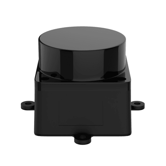 Intermediate
2D LiDAR SLAM: A Controlled slam_toolbox Mapping Baseline
Build a repeatable small-area map only after the MS200 or RPLIDAR C1 scan, motion feedback and TF chain have passed acceptance.
Read tutorial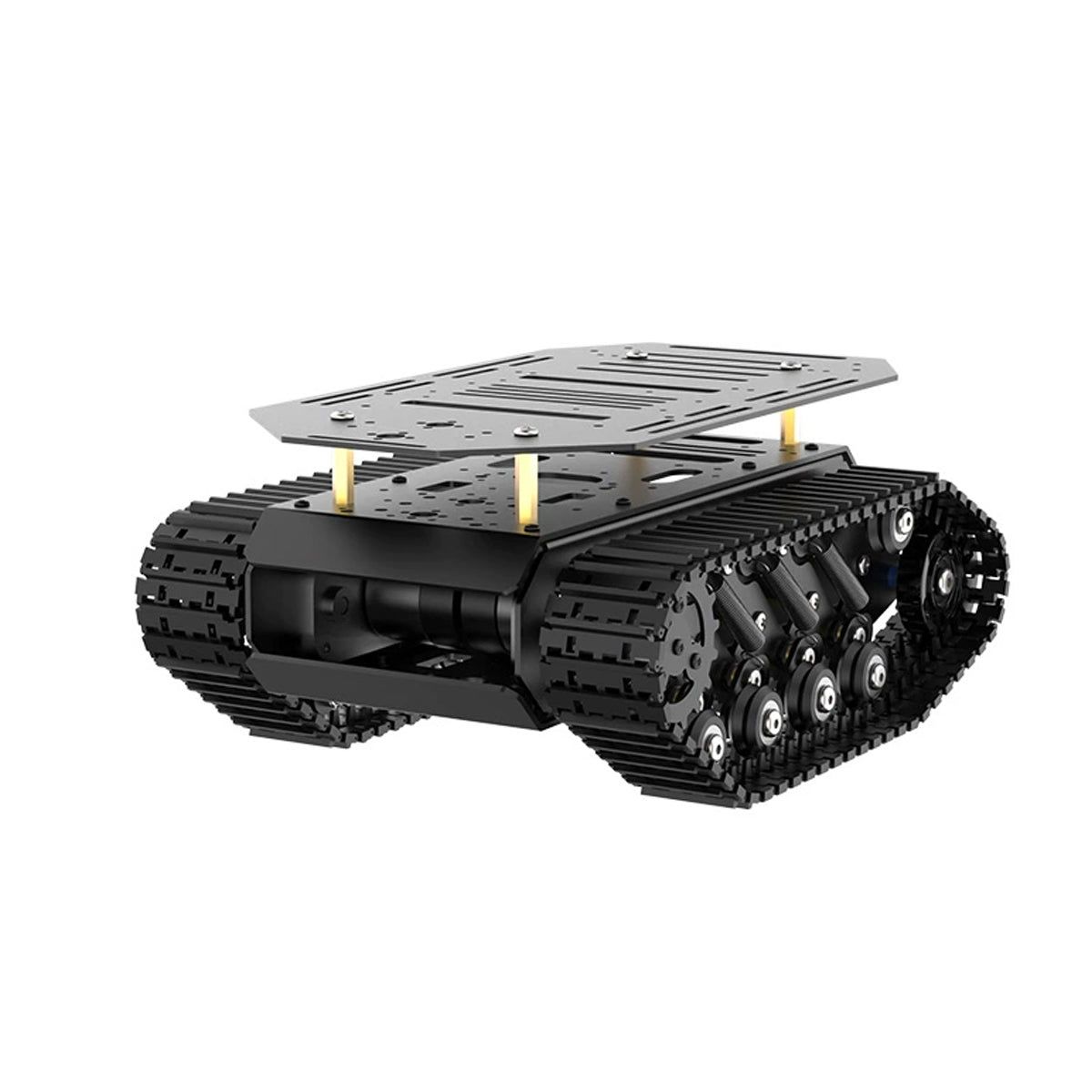 Advanced
Nav2 on a Tracked Robot: Map-to-Goal Supervised Validation
Run a conservative Nav2 localization and goal test only after mapping, motion safety and sensor acceptance are repeatable.
Read tutorialProduct details
Everything you need to evaluate the fit.
Clear product information, technical specifications and compatibility details—kept separate from the purchase decision.
Overview
A 2D navigation sensor, not a depth camera
RPLIDAR C1 is a rotating, single-line fusion dToF LiDAR. Every revolution measures one horizontal plane around the robot, making it suited to mapping, localization and floor-level obstacle perception. It does not measure object height or create an RGB-D scene; use a depth camera or 3D LiDAR when vertical geometry matters.
Choose C1 or COG-MS200-LIDAR deliberately
Both products are 360° 2D dToF LiDARs with UART integration, ROS / ROS 2 workflows and a published 12 m maximum range. They are alternatives, not duplicate listings.
Choose RPLIDAR C1 when the application benefits from its published 5,000 samples/s and 0.72° typical resolution at 10 Hz, the explicitly documented 0.05–6 m range on a 10% reflective black target, IP54 protection, and the RPLIDAR SDK / development-kit ecosystem. Plan for the 55.6 × 55.6 × 41.3 mm, 110 g housing and a 5 V supply that can support its typical 800 mA start-up current.
Choose COG-MS200-LIDAR when a much smaller, lighter 37.7 × 37.5 × 33 mm, 40 g module and compact 4-pin power/UART connection are the deciding constraints. Its published 0.03–12 m figure is specified at 90% reflectivity; do not treat that as equivalent to C1's separately published black-target figure.
Integrate the electrical, optical and coordinate path
C1 uses a 3.3 V TTL UART at 460800 baud (8N1) and a standard XH2.54-5P connector with separate 5 V power. Keep the optical window fully unobstructed, mount the unit rigidly and level, and never assume a translucent cover is acceptable without a scan-quality test. The published scan frame is left-handed: the forward direction is +X and scan angle increases clockwise. Set the actual sensor-to-base transform on the completed robot; the LiDAR cannot infer it for you.
Accept it on the finished robot
Before connecting SLAM or Nav2 behavior, verify stable power at the sensor, raw scan output, scan direction, a known wall/target, frame alignment and representative dark, angled, low and transparent obstacles. Published ranging conditions are not a safety envelope. Keep emergency-stop and robot-specific safe-motion logic independent of the headline range.
Technical specifications
Weight
110 g
Connector
XH2.54-5P: 5 V power, TX, RX and GND
Dimensions
55.6 × 55.6 × 41.3 mm
Protection
IP54
Data output
Distance, angle, scan-start and checksum data; platform materials also describe reflectivity / 2.5D information
Laser safety
IEC 60825 Class 1
Power ripple
≤150 mV
Product role
360° single-line 2D LiDAR for mapping, localization and planar obstacle perception
Data geometry
One horizontal scan plane; objects above or below the plane are not measured
Mounting note
Four M2.5 bottom screws; insertion depth must not exceed 4 mm
Sampling rate
5,000 samples/s (5 kHz)
Data interface
3.3 V TTL UART, 460800 baud, 8N1
Scan frequency
8–12 Hz; 10 Hz typical
Supply voltage
4.8–5.2 V DC; 5 V typical
Ranging accuracy
±30 mm under the published test conditions
Operating current
230 mA typical; 260 mA maximum at 5 V / 10 Hz
Angular resolution
0.72° typical at 10 Hz
Ranging resolution
15 mm
Selection boundary
Choose over COG-MS200-LIDAR for explicit dark-target data, denser 10 Hz sampling and IP54; choose MS200 for much lower mass and tighter packaging
Ambient-light limit
40,000 lux
Optical integration
Keep the optical window unobstructed; validate any cover or enclosure around the scan path
Storage temperature
−20 to 60 °C
Host and software fit
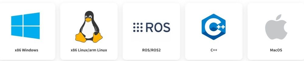
x86 Windows, x86 Linux and ARM Linux; documented ROS / ROS 2 SDK path
Operating temperature
−10 to 40 °C
Measurement technology
Fusion direct time-of-flight (dToF) rotating laser scanning
Outside published range
The sensor may output points below 0.05 m or above 12 m, but the manufacturer does not guarantee their accuracy
Start-up current budget
800 mA typical
Scan coordinate convention
Left-handed; forward direction = +X; scan angle increases clockwise
Published black-target range
0.05–6 m at 10% reflectivity
Published white-target range
0.05–12 m at 70% reflectivity
Shipping & support
Choose your destination at checkout to see the available shipping methods. Need integration advice before ordering? Our support team can help you choose compatible components.
In the box
Package contents
RPLIDAR C1 scanner
360° fusion dToF 2D LiDAR with XH2.54-5P power / UART connection.
USB-to-UART adapter board
Development-kit bridge for attaching the TTL UART LiDAR to a host computer.
USB cable
Host cable for the development-kit USB adapter.
Order configuration check
Verify scanner-only versus development-kit accessories on the order confirmation before installation.
Expert support
Frequently asked questions
How is RPLIDAR C1 different from COG-MS200-LIDAR?
Both are rotating 360° single-line 2D dToF LiDARs for a horizontal navigation scan. C1 is larger and 110 g, but publishes 5 kHz / 0.72° typical resolution at 10 Hz, a 10%-reflectivity black-target range and IP54 protection. MS200 is about 40 g and much more compact with a 4-pin power/UART connection; its 12 m claim is stated at 90% reflectivity. Choose by installed space, target surfaces, power, connector and required protection—not by the shared “12 m” headline.
Does the 12 m C1 range apply to black objects?
No. The published 12 m figure is for a 70% reflective white target. The separately published 10%-reflectivity black-target range is 0.05–6 m. Treat all dark, glossy, transparent and angled obstacles as a final-robot validation item.
Can C1 replace a depth camera or a 3D LiDAR?
No. C1 measures one rotating horizontal plane. It is useful for 2D SLAM, localization and obstacle perception at its installed height, but it cannot describe object height, shelves, overhangs or arbitrary 3D geometry.
Can I use it with Raspberry Pi, Jetson and ROS 2?
Yes, with compatible 3.3 V UART hardware, stable 5 V power and the matching SDK / driver. The published ecosystem supports x86 Windows, x86 Linux, ARM Linux, ROS and ROS 2. Validate the actual serial device, scan orientation and transform on the target host before using a navigation stack.
Can I put C1 behind a plastic or acrylic cover?
Do not assume so. The optical emitter and receiver window must remain clear; a cover can reduce range or increase artifacts. Use a physical opening where possible, or validate the exact material, shape and cleanliness across the required scan field before deployment.
What power and mounting provisions are required?
Use a 4.8–5.2 V supply with no more than 150 mV ripple, budget 800 mA typical start-up current and use the 3.3 V UART at 460800 baud. Mount it rigidly and level, keep the optical path clear, and limit each bottom M2.5 screw insertion to 4 mm.