What this guide proves
COG-RRC-LITE is mechanically mounted, powered within its 6–14 V input range through a verified path, visible to the Raspberry Pi 5, and checked with no unexpected motor or servo activity.
Hardware and scope boundary
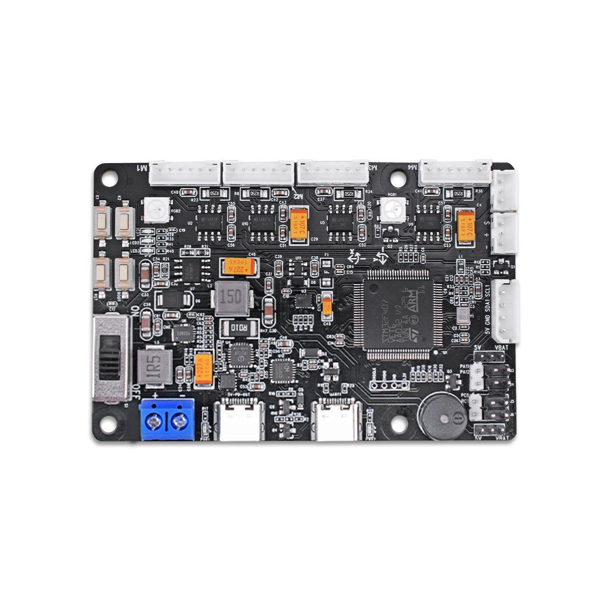
The controller provides four encoder-motor channels, a QMI8658 6-axis IMU, PWM and serial-bus-servo ports, USB/I²C and a Pi 5-compatible 5 V / 5 A host-power path. It is not supplied with a Raspberry Pi, battery, motors or a universal firmware image for every chassis.
Prepare before applying power
Photograph the delivered board, connectors, jumpers and labels. Use the documented power harness only after verifying voltage, polarity and current capability. Disconnect motors and bus servos for the first host-link check; do not feed the Pi from more than one unverified 5 V source.
Procedure
- Mount the board using its 57.5 × 48.5 mm hole pattern with clearance for connectors and strain relief.
- With loads disconnected, inspect reverse-polarity protection, wiring polarity and the selected servo-voltage jumper position. Do not select a servo rail until the attached servo specification is known.
- Apply the verified controller input, observe the expected indicators, and measure or otherwise verify the Pi host-power path before relying on it for a Pi 5.
- Connect the supplied Type-C data cable to the Pi, identify the serial interface, and use the delivered firmware documentation for a read-only version, IMU or heartbeat check.
- Test one motor/encoder channel only after the chassis is safely raised or mechanically restrained. Confirm direction, encoder count direction and stop behavior before connecting further channels.
Pass criteria and record
Record controller serial number, firmware identity, input source, host-link path, jumper positions and one-channel direction test. No reset, unexplained heat, brownout or uncontrolled output is acceptable.
Do not proceed when
Stop if connector pinout or polarity is uncertain, the Pi loses power under a controller transition, a motor moves without an explicit test, or firmware support is not matched to the delivered board.
Continue from here
Add the specific chassis firmware or ROS bridge only after this electrical acceptance. Keep the motor map, encoder counts and power topology with the robot build record.