What this guide proves
The four encoder motors and IMU produce an explicitly documented odometry estimate whose sign, scale and drift behavior have been checked on the actual floor. The output is a calibration baseline, not a claim of globally accurate positioning.
Hardware and scope boundary
COG-L1-MECANUM-BASE is a chassis with four 310 encoder-geared DC motors and AB-phase encoders. It needs a compatible four-channel encoder-motor controller and a regulated power system; COG-RRC-LITE and COG-RPI5-8GB are integration components, not included chassis contents.
Prepare before applying power
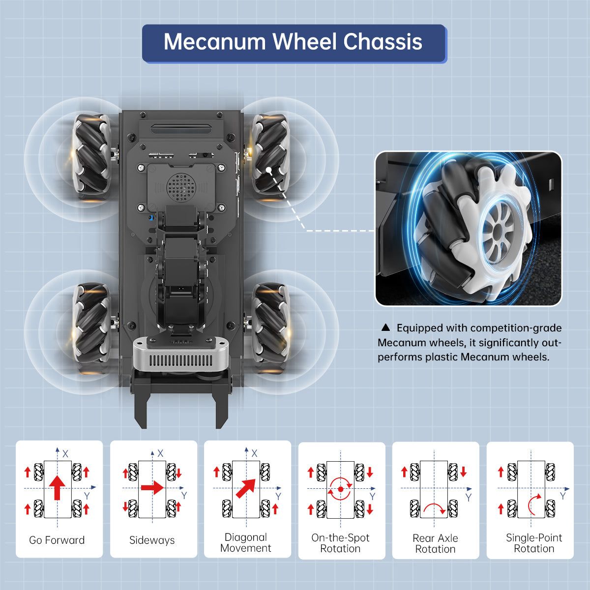
Confirm the left/right Mecanum wheel ABAB arrangement, motor mapping, encoder wiring and wheel direction while the chassis is safely supported. The base is designed for reasonably firm, flat indoor surfaces; roller slip, load and floor texture affect final odometry.
Procedure
- Define base_link and the robot forward, left and up conventions before collecting data. Write the sign convention next to the motor map.
- Test each encoder channel at low speed and record whether counts increase or decrease for the intended wheel rotation. Correct mapping errors at the controller or interface layer.
- Measure the real wheel geometry and use it as an initial parameter; do not substitute a nominal dimension after tires, rollers, load or mounting have changed.
- Drive short forward, lateral, diagonal and yaw-only paths under supervision. Compare estimated displacement and yaw against measured floor marks.
- Check the QMI8658 IMU axis convention and stationary bias. Fuse or compare data only after timestamps, units and frame orientation are understood.
Pass criteria and record
Save the chassis configuration, encoder sign map, wheel parameters, IMU orientation, floor type and test error for each motion pattern. A later team member must be able to repeat the same tests.
Do not proceed when
Do not pass odometry onward if a wheel map is ambiguous, a wheel is slipping excessively, IMU axes are unknown, timestamps are inconsistent, or measured errors change unpredictably between runs.
Continue from here
Use the documented frames in URDF/TF, then assess the chosen controller interface or ros2_control configuration before mapping.