 1 / 1
1 / 1Cogalloy L1 6-DOF Bus-Servo Arm Module
A calibrated 6-DOF bus-servo arm module with gripper, six HX-06L intelligent servos and an anodized-aluminum structure for Cogalloy L1 mobile-manipulation builds. It needs a protected 6–8.4 V servo rail and a half-duplex UART controller at 115200 baud. The 410 mm reach and 100 g payload are planning references, not a guarantee on a moving robot.
- 6 calibrated bus-servo axes: Six HX-06L servos, gripper and anodized-aluminum structure for compact manipulation experiments.
- 410 mm / 100 g planning envelope: Reference reach and payload figures that must be validated for the final pose, load and base motion.
- Feedback on one 115200-baud bus: Angle, voltage and temperature feedback with configurable servo IDs over a half-duplex UART bus.
- Module scope made explicit: Arm assembly only: chassis, controller, Pi, depth camera, LiDAR and power system are separate items unless ordered.
Price
US$129.99
No account or payment needed. We usually confirm availability, lead time, shipping, and total price within 12 hours.
Or email us directly: sales@cogalloy.comShipping options and final delivery cost are shown at checkout.
PRODUCT SCOPE
Buy the arm module—not an implied complete robot.
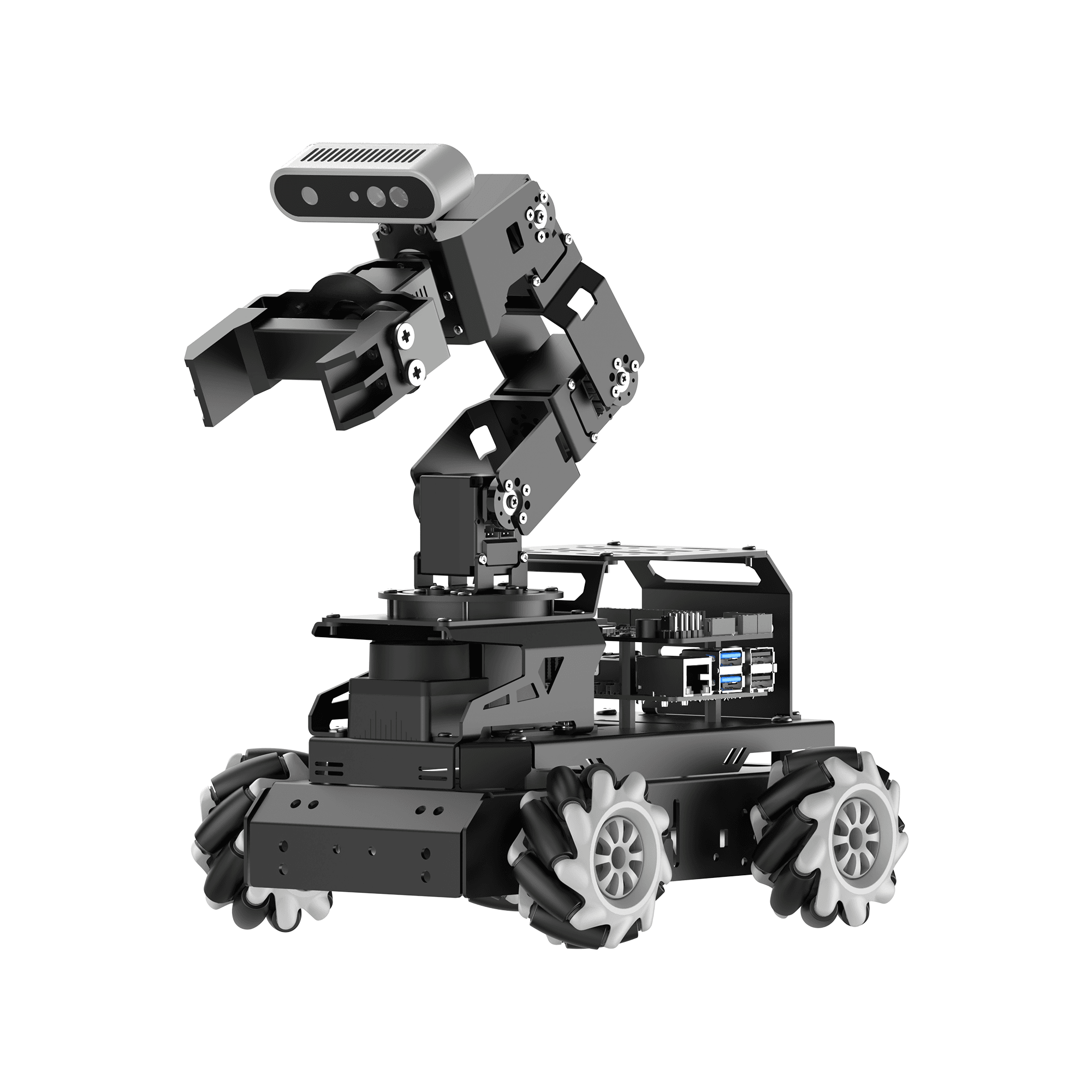
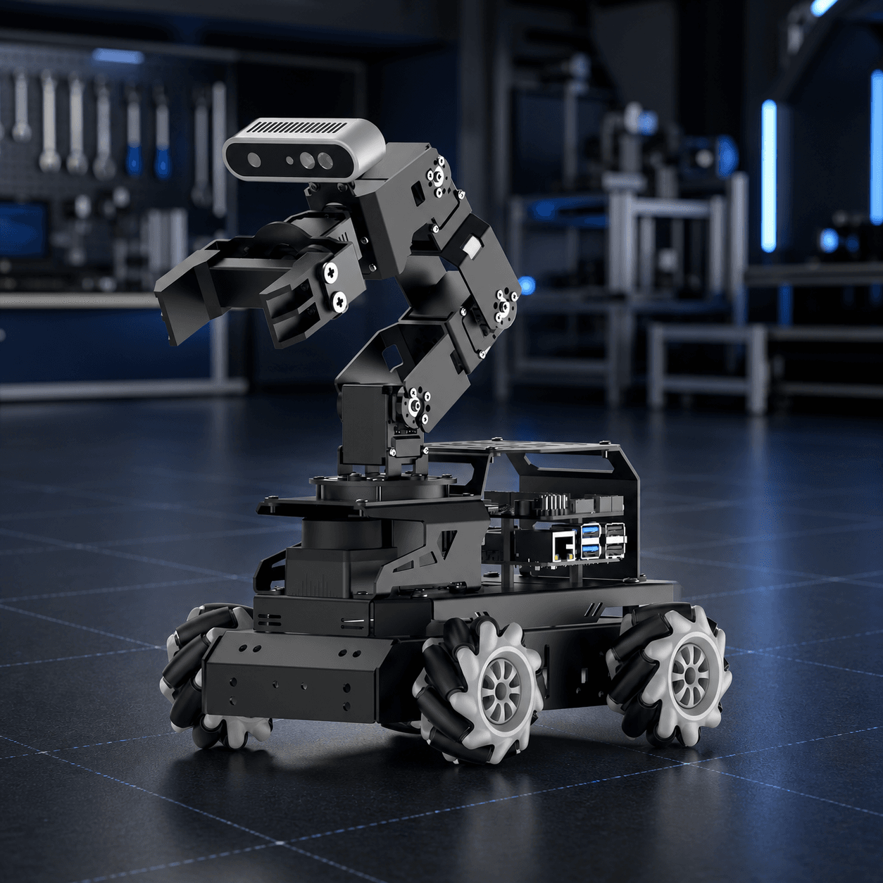
This SKU is the 6-DOF manipulation assembly with gripper. It is designed to mount on a compatible base or fixture. The image illustrates a fully configured mobile robot, but the chassis, controller, computing, depth camera, LiDAR, battery and charger are not included unless explicitly listed in the order.
- Six HX-06L bus servos, metal structure and gripper are the arm-module core.
- Use a compatible controller and a separate protected 6–8.4 V servo power path.
- Confirm every accessory on the order confirmation before assembly.
ACTUATION + FEEDBACK
Control six joints on one bus, then validate every joint.
The arm uses six HX-06L intelligent serial servos at 115200 baud. Position readback, voltage and temperature feedback make commissioning observable, but the host must still allocate IDs, apply joint limits and define safe motion. Servo protection is a last layer—not a collision controller.
- DC 6–8.4 V, 7.4 V nominal; do not power the arm from a 5 V computer rail.
- Published servo values: 6 kg·cm at 7.4 V, 0.2 s / 60°, 0–240° position range and 0.3° precision.
- Use unique IDs and validate direction, zero and cable clearance at low speed before any trajectory.
WORKSPACE + LOAD
Treat reach and payload as a system envelope.
The published 410 mm reference reach, radius ≤23 cm gripping range and 100 g payload help size an experiment. The usable volume becomes smaller when a gripper, camera, cable bend radius, acceleration, obstacle clearance or moving chassis are introduced.
- Validate payload at the planned pose, not only close to the base.
- Do not run high-speed trajectories at maximum extension until the base and collision envelope are verified.
- A depth camera can support grasp perception only after camera-to-arm and arm-to-base transforms are checked.
COMMISSIONING
A controlled acceptance sequence prevents a bad first motion.
A matching complete configuration ships calibrated, but any separate integration needs a deliberate bring-up. Start with an empty workspace, stable base and supervised low-speed motion; then check neutral positions, end-effector travel, feedback and transforms before attempting a grasp.
- Power → identify servos → verify neutral pose/direction → low-speed single-joint tests.
- Confirm collision limits, gripper opening and cable strain relief through the full reachable path.
- Only then add perception, inverse kinematics and autonomous grasping logic.
Product details
Everything you need to evaluate the fit.
Clear product information, technical specifications and compatibility details—kept separate from the purchase decision.
Overview
A manipulation module, not a complete mobile robot
Cogalloy's L1 6-DOF arm module is the articulated manipulation assembly: six HX-06L intelligent bus servos, anodized-aluminum brackets and a gripper. It is designed to add controlled reach and grasping experiments to a compatible mobile base or bench fixture. The product is deliberately scoped as an arm module; it is not a bundled mobile robot, Raspberry Pi, low-level controller, depth camera, LiDAR, battery, charger or power supply.
The product imagery shows the arm in a complete mobile-robot context to explain fit. That image is not a packing-list promise: camera, chassis, controller and other visible components must be ordered separately unless they are explicitly named on the order confirmation.
Mechanical envelope: use it as a planning input
The documented arm has 6 degrees of freedom, a 410 mm reference reach, an effective gripping radius of up to 23 cm and a 100 g reference payload for gripping and handling. Those figures are useful for early layout and demo planning. Actual usable workspace and payload depend on the end effector, joint pose, acceleration, cable drag, base rigidity, moving-base posture and collision limits. Do not plan a mobile pick sequence to the maximum reach without validating it at the actual speed and load.
One serial bus, a real power budget
Six HX-06L servos share a half-duplex UART bus at 115200 baud. Each servo supports position readback plus temperature and voltage feedback, retains user settings after power-off, and includes stall and over-temperature protection. The servo operating range is 6–8.4 V (7.4 V nominal); it is not a 5 V Raspberry Pi accessory. Build a protected servo power path with appropriate wiring, fuse/current margin and a controller that supports the required UART protocol. A servo can draw up to 1.3 A at stall, so a system must be designed for its real motion profile rather than the no-load number alone.
Commission before autonomous motion
A matching full configuration is factory-calibrated, but mounting changes, transport, a new controller, a new gripper or a changed camera transform require verification. First confirm servo IDs, neutral pose, joint directions, cable clearance and a clear workspace at low speed. Then validate joint limits, collision envelope, camera-to-arm transform and object-handling motions. Safe stops, speed limits and human clearance must be implemented by the host robot; feedback and servo protection are not a substitute for system safety.
Technical specifications
Servo IDs
User-configurable 0–253; confirm unique IDs before operation
Structure
Anodized aluminum-alloy brackets and metal-gear bus servos
Protection
Stall protection and over-temperature protection listed for the servo system
Control bus
Half-duplex UART serial bus, 115200 baud
Servo speed
0.2 s / 60° at 7.4 V
End effector
Mechanical gripper driven as one of the six bus-servo axes
Not included
Mobile chassis, low-level controller, Raspberry Pi, depth camera, LiDAR, battery, charger and power supply unless explicitly stated in the order
Servo memory
User settings retained after power-off
Servo torque
6 kg·cm at 7.4 V
Product scope
Standalone 6-DOF arm module with gripper for Cogalloy L1 mobile-manipulation or bench integration
Position range
0–240° (command value 0–1000)
No-load current
300 mA per servo published
Operating modes
Position servo mode and continuous motor mode; use position mode for articulated-arm motion
Servo connector
5264-3P / SIG, VIN, GND bus connection
Reference payload
100 g for gripping and handling; validate at the actual pose, speed and mobile-base state
Software boundary
The module supplies actuation and feedback. Grasp planning, collision checking, transforms, speed limits and safety behavior belong to the host system
Calibration status
A matching complete configuration is factory-calibrated; recheck neutral pose and offsets after transport, mounting or mechanical changes
Camera integration
An end-of-arm depth camera may be used in a complete robot configuration but is not included with this arm module
Degrees of freedom
6
Included actuation
HX-06L intelligent bus servo ×6
Reference arm reach
410 mm
Readback and feedback
Angle readback plus temperature, voltage and position feedback
Controller requirement
Compatible 6–8.4 V bus-servo power and half-duplex UART controller; Raspberry Pi GPIO / 5 V rail alone is not sufficient
Mobile-base integration
Rigid mounting, cable strain relief, joint clearance, an established arm-to-base transform and a stable base are required
Servo operating voltage
DC 6–8.4 V; 7.4 V nominal
Stall-current reference
1.3 A per servo published; size the servo supply and protection for the real simultaneous-load case
Servo positioning precision
0.3° published
Reference effective gripping range
Radius ≤23 cm
Shipping & support
Choose your destination at checkout to see the available shipping methods. Need integration advice before ordering? Our support team can help you choose compatible components.
In the box
Package contents
Cogalloy 6-DOF bus-servo arm assembly
Articulated arm with gripper, six HX-06L intelligent bus servos and anodized-aluminum mechanical structure.
Arm bus wiring and mechanical fasteners
The supplied lead and mounting hardware follow the final module configuration. Confirm the exact contents on the order confirmation before installation.
Integration and calibration materials
Use the matching servo protocol, wiring, mounting and calibration materials for the delivered configuration. Recheck neutral position after a mechanical change.
Items deliberately excluded
Mobile chassis, controller, Raspberry Pi, depth camera, LiDAR, battery, charger and regulated servo power supply are not included unless explicitly named in the order.
Expert support
Frequently asked questions
Does this SKU include the full Cogalloy L1 robot, camera or controller?
No. This SKU is the 6-DOF arm module with gripper. It does not include the mobile chassis, low-level controller, Raspberry Pi, depth camera, LiDAR, battery, charger or power supply unless the order explicitly lists them. The gallery image shows a complete integration context, not a default packing list.
What controller and power supply does the arm need?
Use a controller that supports the HX-06L half-duplex UART bus at 115200 baud and a protected 6–8.4 V servo supply (7.4 V nominal). Do not drive the arm from a Raspberry Pi 5 V rail. Each servo has a published 1.3 A stall-current reference, so size wiring, fuse/current margin and protection for the real simultaneous-load case.
What do the 410 mm reach and 100 g payload mean in practice?
They are published planning references, not a guarantee for every pose. Usable reach and payload depend on extension, gripper, acceleration, cable drag, mounting, obstacle clearance and mobile-base posture. Test the actual object at the intended pose and motion speed before deployment.
Can I use it for autonomous grasping with ROS 2 or MoveIt?
Yes, as an actuator module in a compatible system. You still need a controller/driver, joint limits, a calibrated arm-to-base transform, collision model, perception-to-arm transform, inverse kinematics and robot-specific safety behavior. The arm alone does not make a grasp autonomous.
Is a depth camera included?
No. A depth camera can be mounted in a complete mobile-robot configuration, but it is a separate product. If you add one, calibrate the camera-to-end-effector transform and verify the complete geometry before using it for grasping.
Does it require calibration after delivery or a mechanical change?
A matching full configuration is factory-calibrated, but always inspect neutral position, IDs, joint direction and cable clearance after transport or installation. Recalibrate / restore offsets if the arm no longer reaches the expected pose after a mechanical change.
Are the servo feedback and protection features enough to make it safe?
No. Position, voltage and temperature feedback plus stall/over-temperature protection help monitor actuator health, but they do not provide collision avoidance, speed limits, emergency stop or human safety. Those controls must be implemented and tested at the robot level.