Selection & Case Study
Selection case: a mobile-platform power budget beyond battery capacity
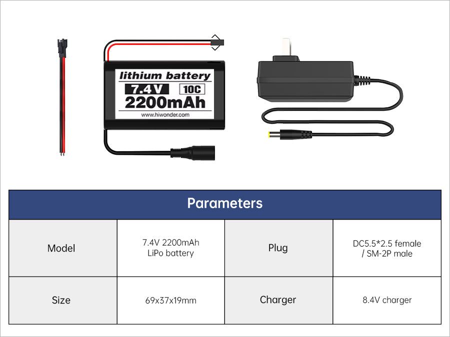
A power-selection case that separates energy, peak current, connector compatibility and regulated rails before a mobile robot is assembled.
The case: a robot reboots when the chassis moves
A battery capacity number answers only part of the question. A mobile robot can have enough stored energy for an hour and still reset its computer the first time motors accelerate, a servo stalls or a LiDAR starts.
The useful selection outcome is a stable set of power rails under real transitions: the drive system can draw its transient current, the controller stays within input range, and the host and sensors remain on a clean regulated supply.
Separate energy from peak behavior
Estimate energy in watt-hours for runtime planning, then make a separate table for expected continuous and transient loads. Include motor startup and stall references, controller conversion losses, host compute, cooling, sensors, USB peripherals and any servo rail.
Do not turn a battery C label into a universal promised current. Use the delivered pack label, protection behavior, connector, wire gauge and target-system test to establish what the actual design can support.
Two current product paths must not be conflated
COG-7V4-2200-LIPO is a 7.4 V 2200 mAh protected pack with DC 5.5 × 2.5 mm and SM-2P connectors, and requires a verified 8.4 V charge path. It is suitable only for a compatible system after voltage, polarity, connector and load evidence are checked.
COG-T1-TRACK-BASE already lists a different 11.1 V / 6000 mAh pack and 12.6 V charger in its chassis configuration. It is not safe to substitute or parallel these packs based on connector appearance or capacity alone.
Define rails, ownership and failure behavior
Document which source feeds motor drive, which regulator feeds COG-RRC-LITE, which verified 5 V / 5 A path feeds COG-RPI5-8GB, and where LiDAR, RGB-D and servos take power. A power diagram should also show fuse/protection ownership and the physical disconnect method.
The Raspberry Pi is a high-level host, not a motor supply. It must not be used as an assumed source for drive motors or a six-servo arm. Keep high-current transients and sensitive compute/sensor supply behavior observable and separately testable.
Acceptance sequence
Begin with a visual and connector/polarity inspection. Power the host and sensors without motion, then add one controlled motor channel, then representative chassis movement, then the expected sensing and compute load. Record voltage and reset behavior at each gate.
Charge only with the specifically verified charger and procedure. A damaged, hot, swollen or unidentified pack is a stop condition, not a component to troubleshoot in a completed robot.
Decision record
The final record names every pack, charger, harness, regulator, fuse/protection element and load class, with observed voltage behavior. It includes the conditions used for any runtime observation rather than presenting a single runtime number as universal.
This turns a battery selection into a controlled system decision and gives later changes—a new camera, arm or compute load—a clear place to be evaluated.
Ready to turn the method into specific parts?
Browse the parts catalogue